

Fiber Optic Testing
This is your “QuickStart” guide to testing optical power in fiber optic communications systems with a fiber optic power meter. We’ll give you the basic information you need and provide some printable references. Just go to the topics below to find the information you need. Links to videos and more comprehensive information will be provided in each section.
Testing Communications Equipment For Optical Power Levels
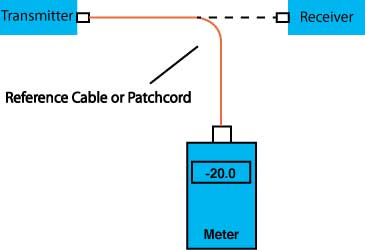
Fiber optic communications equipment depends primarily on having the proper optical power levels, especially the output power of the transmitter and the power at the receiver. The difference between these two power levels is the loss of the cable plant which can be tested as described above.
This test will measure the optical power exiting the end of a fiber optic cable. This test is commonly used to measure the coupled power of a fiber optic source in a transmitter using a reference cable or the patchcord connecting the source to the cable plant or the power into a receiver measured by unplugging the cable connected directly to the receiver. The method shown is on the FOA “1 Page Standard” FOA3 which you may print or download and insert in your documentation.
Equipment Needed To Perform This Test
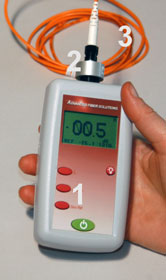
1. Fiber optic power (#1) meter calibrated at the same wavelength as the source output (e.g. multimode: 850 or 1300nm, singlemode, 1310, 1490 and/or 1550 nm, POF 650 nm) capable of measuring optical power in the power range of the source.
2. Optical power meter adapters (#2) to mate to connector type on cable.
3. Reference cable (#3) or known good patchcord (tested using the method above) that is the same fiber type and size as the cable plant and have connectors compatible to those on the source and cables.
4. Cleaning supplies
Test Procedure
1. Turn on meter and allow time to warm-up
2. Set meter to wavelength of source and “dBm” to measure calibrated optical power.
3. Clean all connectors and mating adapters.
4. Attach reference cable or patchcord to source if testing source power or disconnect cable from receiver.
5. Attach power meter to end of cable and read measured power.
Options For Testing
Power is generally measured in “dBm” or dB referenced to 1 milliwatt of optical power. Optical power measurements may also be made in Milliwatts (mW) or microwatts (µW)
Reducing Measurement Uncertainty
1. Calibrate optical power meter according to manufacturer specified intervals.
2. Clean all connectors and remove meter adapter periodically to clean the adapter and power meter detector.
3. Do not bend fiber optic cables tightly to cause stress loss.Documentation
Documentation
Record the following data to document your tests and keep copies for future reference:1. Date of the test
2. System being tested and identification
3. Operator
4. Test equipment used
5. Test wavelength
6. Measured optical powerSource :FOA


![download[4]](http://edwardsync.net/wp-content/uploads/2016/03/ezgif-1447380043.gif)